
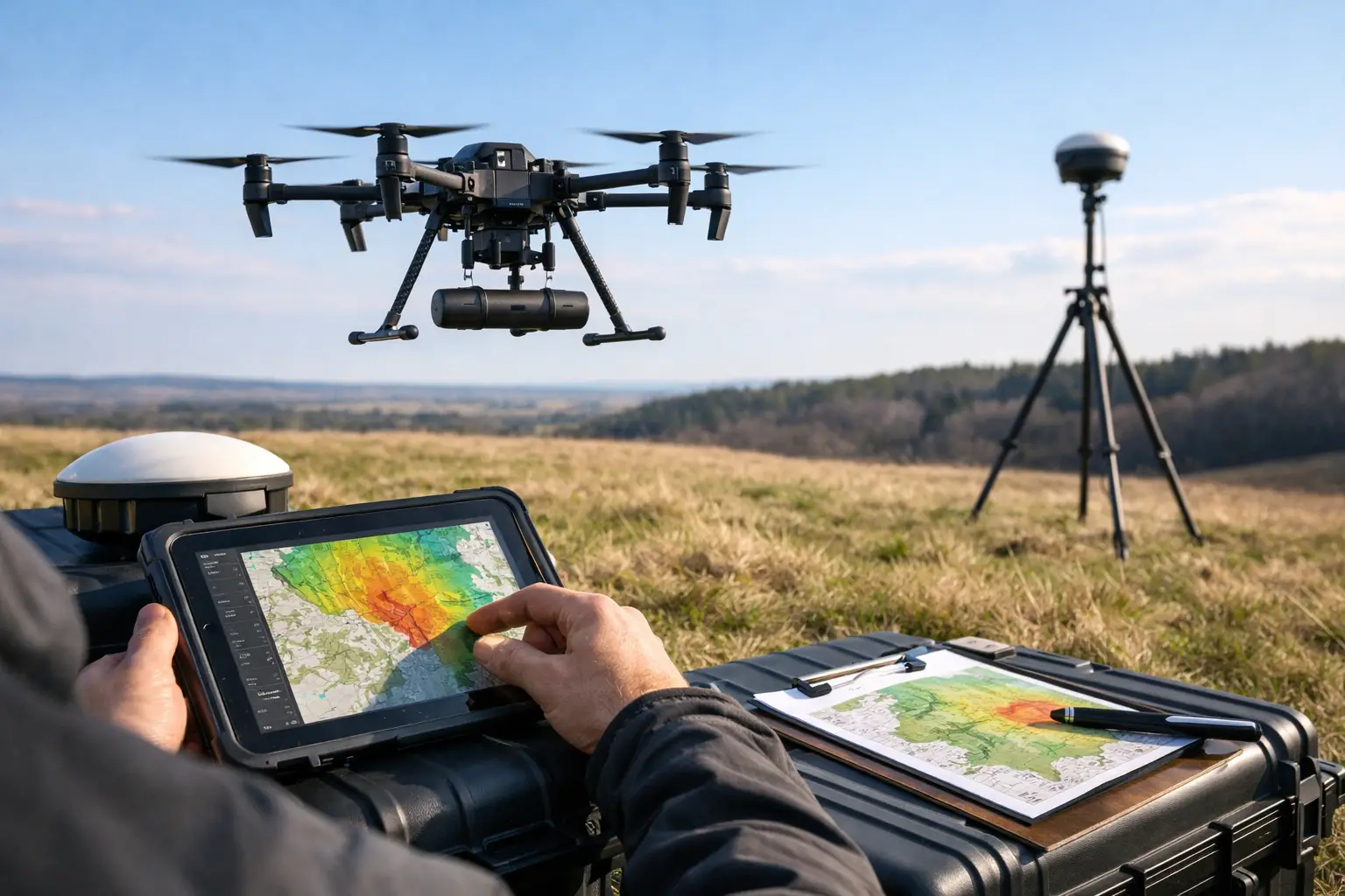
A magnetic anomaly is only valuable when the acquisition geometry, sensor configuration, and quality controls support the decision behind the survey. Knowing how to plan drone magnetometer survey work is therefore not a flight-planning exercise. It is a technical design process that converts a geological, engineering, or infrastructure question into calibrated, traceable magnetic data and interpreted intelligence.
For mineral exploration, the objective may be to resolve structural controls, intrusive contacts, or alteration-related magnetic signatures beneath shallow cover. For utilities, infrastructure, or groundwater programs, the priority may be mapping buried ferrous features, basement structure, or fault trends. Each objective demands different line spacing, flight altitude, sensor selection, processing controls, and reporting criteria.
Start With a Decision, Not a Sensor
The first planning question is not which drone or magnetometer to deploy. It is what decision the data must support. Define the target features, their expected scale, the area of investigation, and the level of uncertainty that must be reduced.
A regional structural mapping program can tolerate wider line spacing and higher terrain clearance than a detailed target-generation survey. Conversely, a near-surface engineering investigation may require tight line spacing, low and consistent sensor altitude, and careful separation of cultural magnetic interference from meaningful subsurface responses.
The project brief should establish the survey boundaries, target depth range, expected anomaly wavelength, required spatial resolution, and deliverables. It should also identify whether the client needs total magnetic intensity only, magnetic gradients, reduced-to-pole products, derivative grids, structural interpretation, or cross-validation against LiDAR, photogrammetry, radiometrics, or ground data.
This stage prevents a common failure: collecting visually impressive magnetic maps that are not fit for geological interpretation or engineering design.
Build the Survey Geometry Around the Target
Flight-line orientation, spacing, altitude, and tie-line design determine whether an anomaly is resolved accurately or smeared into an ambiguous feature. Survey geometry must be selected from the anticipated geology and the required resolution, not from a generic operational template.
Select line direction and spacing
Production lines are generally oriented perpendicular to the dominant geological strike where that strike is known. This maximizes the magnetic response across contacts, faults, dikes, and lithological boundaries. If structural orientation is uncertain or highly variable, a reconnaissance design may use broader coverage followed by an infill survey over priority zones.
Line spacing should be appropriate to the smallest feature that needs to be mapped. Tighter spacing improves spatial definition but increases flight hours, battery cycles, processing volume, and cost. Wider spacing is efficient for regional screening but can miss narrow structures or produce aliasing. The correct design is therefore a balance between target scale, budget, terrain constraints, and the confidence required for the next investment decision.
Tie lines should cross production lines at a planned interval and provide sufficient control for leveling. Their purpose is not administrative. Tie-line intersections expose line-to-line offsets, heading effects, and residual drift that must be corrected before gridding and interpretation.
Control sensor altitude and terrain clearance
Magnetic signal strength declines rapidly with distance from the source. Low-level acquisition improves resolution, but only when it can be flown safely and consistently. In rugged terrain, a terrain-following plan based on a reliable digital elevation model is often essential to maintain a stable drape surface.
Absolute altitude alone is not enough. The processing team needs a clear record of terrain clearance, actual flight path, velocity, attitude, and data gaps. Significant variations in sensor height can create amplitude changes that resemble geology. This is especially relevant across escarpments, wadis, infrastructure corridors, and disturbed industrial terrain.
Design the Platform and Sensor Configuration
A drone magnetometer survey introduces magnetic noise sources that do not exist in the same form during conventional aircraft acquisition. Motors, batteries, wiring, payload mounts, and airframe components can all influence the measurement. The platform must be characterized before production, not assumed to be magnetically clean.
The magnetometer should be mounted at a validated separation from the aircraft, typically using a boom, suspension arrangement, or other configuration proven through test flights. The goal is to reduce platform-induced interference while preserving stable flight behavior and operational safety. Sensor placement is a trade-off: greater separation can reduce interference, but it may increase payload dynamics and operational complexity.
Pre-survey testing should quantify static interference, dynamic noise, heading response, vibration effects, and electromagnetic coupling. Calibration flights and repeat lines are used to assess whether the combined aircraft-sensor system can meet the project noise threshold. A technically defensible survey documents these tests and retains the evidence within the QA/QC record.
Establish Positioning, Timing, and Base-Station Control
Magnetic data without reliable spatial and temporal control cannot support audit-ready interpretation. Every sensor stream must be synchronized to a common time reference, including magnetometer readings, GNSS position, altitude, inertial measurements, and base-station observations.
A ground magnetic base station records temporal variations in the Earth's magnetic field during flight operations. These diurnal changes can be significant enough to obscure subtle anomalies if they are not measured and corrected. The base station should be installed in a magnetically quiet location, away from vehicles, generators, fences, buried utilities, and active equipment.
Base-station data must be reviewed against the flight timeline. If magnetic activity is excessive, the acquisition window may not be suitable for precision work. Repeating affected lines is usually less costly than attempting to defend compromised data after processing.
Positioning requirements depend on the survey purpose. Exploration reconnaissance may accept a different horizontal and vertical accuracy standard than corridor mapping or infrastructure design. For all cases, the planned accuracy, correction method, coordinate reference system, geoid model, and deliverable projection should be defined before mobilization.
Plan for Desert and Industrial Operating Conditions
Environmental and site conditions influence data quality as directly as equipment selection. High temperatures affect battery performance, payload endurance, and operational tempo. Wind can alter line tracking and sensor stability. Dust, restricted airspace, active plant operations, powerlines, pipelines, and vehicle movement all introduce constraints that must be addressed in the method statement.
A disciplined field plan includes launch and recovery locations, battery logistics, communication procedures, emergency contingencies, weather thresholds, exclusion zones, and daily production targets that do not pressure the crew to accept marginal conditions. In Saudi Arabia and other harsh operating environments, thermal management and conservative energy reserves are operational requirements, not optional refinements.
Cultural magnetic noise also requires early reconnaissance. Fences, rail lines, transmission infrastructure, drilling equipment, scrap metal, and parked vehicles can generate responses far stronger than the target anomaly. The survey boundary, flight height, and interpretation workflow should account for these sources so they are identified rather than misclassified.
Define QA/QC Before the First Flight
QA/QC is most effective when it is built into acquisition rather than applied as a final processing step. The field team should review line coverage, altitude compliance, speed consistency, sensor health, GNSS continuity, base-station recording, and preliminary magnetic profiles after each flight block.
Repeat lines are particularly valuable. They provide an independent measure of repeatability under the same acquisition conditions and reveal whether apparent anomalies are persistent geological signals or platform, navigation, or environmental artifacts. Crossovers between production and tie lines should be monitored for residual mismatch, then investigated before demobilization.
The acceptance criteria should be documented in advance. Depending on project requirements, these may include maximum allowable magnetic noise, line deviations, terrain-clearance tolerance, data-gap limits, crossover residuals, and repeat-line correlation. This creates a fully auditable basis for deciding whether a line is accepted, re-flown, or excluded.
Process for Interpretation, Not Just Visualization
Processing should preserve a traceable path from raw observations to final grids and interpreted products. A typical workflow includes time synchronization, despiking, diurnal correction, compensation where applicable, line leveling, micro-leveling, gridding, and derivative generation. Every correction must be controlled, versioned, and reviewable.
The final product selection depends on the question being asked. Total magnetic intensity may support broad lithological mapping, while vertical derivatives can sharpen shallow edges and structural trends. Analytic signal and tilt derivative products can assist with source-edge interpretation, but no transform should be treated as a substitute for geological context. Each emphasizes some aspects of the signal while potentially amplifying noise or obscuring deeper sources.
Where project risk justifies it, magnetic results should be integrated with other datasets. LiDAR can improve terrain control and structural mapping. Photogrammetry can provide current surface context. Electromagnetic, radiometric, geochemical, borehole, and field observations can constrain the interpretation. The result should be a decision-grade model, not a collection of disconnected sensor outputs.
Specify Deliverables That Can Be Defended
A professional scope should define more than a color grid. It should require raw and corrected data, flight logs, base-station records, calibration evidence, QA/QC statistics, coordinate system documentation, gridded products, map layouts, and an interpretation report that states assumptions and limitations.
Air Solutions approaches drone magnetometer programs as integrated geospatial intelligence assignments: acquisition design, controlled field execution, documented processing, and sector-specific interpretation are treated as one accountable workflow. That approach matters when survey outputs inform drilling priorities, route selection, resource models, or capital planning.
The strongest survey plan is the one that makes the next decision easier to defend. Define that decision first, then engineer every line, sensor setting, control point, and quality check around it.