
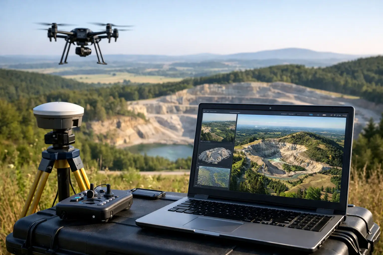
A drone terrain modeling workflow fails long before processing if the project begins with an undefined decision requirement. A surface model that is visually impressive but lacks control, calibration records, or clear accuracy criteria cannot reliably support mine planning, earthworks quantities, drainage design, corridor engineering, or asset-risk assessment. For industrial programs, the deliverable is not a drone flight. It is a traceable terrain dataset with known limitations and a documented chain of custody.
Start With the Decision, Not the Sensor
Terrain modeling requirements vary materially by use case. A preliminary site screening may require broad-area coverage and relative elevation trends. A construction payment survey may require tighter vertical accuracy, established coordinate control, defined breaklines, and a calculation method that can withstand commercial review. A mine expansion project may require both bare-earth terrain and a surface model that captures stockpiles, benches, haul roads, and highwalls.
The first technical step is to define the required surface, coordinate reference system, area of interest, target ground sampling distance, vertical tolerance, and reporting format. This specification should also state whether vegetation, standing water, reflective roofs, active equipment, or steep terrain are expected to affect the model. These conditions determine whether photogrammetry, LiDAR, or a combined acquisition approach is appropriate.
Photogrammetry can produce high-density visual products and accurate surfaces when image geometry, lighting, texture, and ground visibility are favorable. LiDAR is generally better suited to irregular terrain, low-texture ground, complex industrial features, and partially vegetated corridors. Neither system removes the need for control, calibration, or independent validation.
Establish Survey Control Before Mobilization
Control is the reference framework that turns drone-derived measurements into engineering-grade spatial information. It should be planned before flight lines are designed, not added after acquisition to improve a processing result.
A disciplined control plan begins with the project datum and vertical reference. Teams must verify whether elevations are required relative to an ellipsoid, a geoid model, local benchmark network, or a project-specific vertical datum. Confusion at this stage can introduce meter-scale elevation errors into an otherwise precise dataset.
Ground control points provide positional constraints during processing. Checkpoints are held back from the adjustment and used only to test the final model. That distinction is essential. A dataset assessed only against points used to build it is not independently validated.
Control locations should be stable, accessible, well distributed across the project boundary, and represented across changing terrain. On a long utility corridor, control must account for the length and elevation range of the route. On a mine site, points should span benches, low areas, high ground, and the outer limits of the survey. Field teams should record point occupation methods, antenna heights, observation times, coordinates, photographs, and any site-specific constraints. These records establish auditability when the model is reviewed months later.
Design the Acquisition for Terrain Geometry
Flight planning is an engineering activity, not a generic mission template. The aircraft, sensor, flight altitude, overlap, speed, scan geometry, and timing must be matched to the terrain and decision requirement.
For photogrammetry, forward and side overlap must support reliable image matching across the full site. Low-texture surfaces such as sand flats, uniform aggregate, water, and recently graded ground may require increased overlap or alternative sensing. Oblique imagery can improve representation of slopes, structures, and vertical faces, but it also adds processing complexity and should be specified deliberately.
For LiDAR, point density alone is an incomplete quality measure. Scan angle, pulse repetition rate, flight-line overlap, platform trajectory quality, sensor calibration, and terrain occlusion all affect the resulting surface. Steep benches, wadis, transmission corridors, and industrial facilities frequently require cross-lines or multiple viewing geometries to reduce shadowing.
Desert conditions introduce additional operational variables. Heat can affect battery performance and sensor stability. Wind influences platform attitude and image sharpness. Dust, haze, and low sun angles can degrade imagery and create shadow-driven classification errors. Operations should be scheduled around forecast conditions and include sensor checks before and after each sortie. A rapid mobilization does not justify uncontrolled acquisition.
Capture Redundancy and Independent Evidence
Mission redundancy protects the final terrain model from localized data gaps, poor image blocks, GNSS interruptions, or degraded sensor performance. It may include overlap between adjacent flight blocks, cross-flight lines, repeat coverage of critical areas, and independent base-station or network correction records.
Field crews should review coverage and preliminary quality indicators while still on site. Identifying a gap in a haul road, drainage channel, or proposed foundation zone during acquisition is inexpensive. Finding it after demobilization may delay a design package or require a second mobilization.
Process From Raw Data to Controlled Surfaces
Processing should preserve raw observations and create a documented path from source data to final deliverables. The workflow typically includes data ingestion, trajectory processing, calibration review, image alignment or point-cloud generation, georeferencing, classification, surface construction, and validation.
For photogrammetric projects, image alignment is evaluated for camera positions, tie-point distribution, reprojection error, and block geometry. Control points are then introduced through a controlled adjustment, while checkpoints remain excluded. Dense reconstruction should be reviewed for voids, distortion, and false surfaces caused by moving equipment, repetitive patterns, glare, or poor ground texture.
For LiDAR projects, trajectory processing combines GNSS and inertial measurement data to establish the sensor path. Boresight calibration aligns the laser scanner with the navigation solution. Overlap between flight lines is then analyzed for elevation differences. A visually clean point cloud is not sufficient; line-to-line consistency must be measured and reported.
The point cloud must next be classified. Ground classification separates terrain from vegetation, vehicles, buildings, stockpiles, utilities, and other above-ground features. Automated routines accelerate this task, but they require manual review in complex terrain. Aggressive filtering can erase narrow berms, channel edges, retaining structures, and small drainage features. Conservative filtering can leave objects that artificially elevate the terrain model. The correct setting depends on the intended use of the surface.
Build the Right Model for the Use Case
Two terrain products are often confused. A digital surface model represents the uppermost observed surface, including buildings, vegetation, equipment, and stockpiles. A digital terrain model represents bare earth after non-ground features have been removed. Engineering and hydrology teams may need both, but they should not be used interchangeably.
Surface construction requires choices about interpolation, grid size, breaklines, void handling, and edge treatment. A very fine grid can imply detail that the source data does not support. A coarse grid can suppress operationally significant features. Breaklines are especially important where the terrain changes abruptly, such as curb lines, drainage channels, crest lines, toe lines, and excavation edges.
For volume calculations, the baseline surface and comparison date must be controlled consistently. Differences in datum, classification rules, grid resolution, or boundary definition can produce apparent volume changes that are processing artifacts rather than actual earth movement. The calculation method, exclusion areas, and uncertainty assumptions should accompany the result.
Validate Accuracy and Report Uncertainty
Validation converts a model from plausible to defensible. Independent checkpoints should be compared against the final terrain surface, with horizontal and vertical residuals reported using clear statistical measures. Root mean square error is useful, but it should not be the only metric. Maximum error, bias, point distribution, and the number of tested checkpoints provide necessary context.
Accuracy must also be evaluated spatially. A project can meet an overall statistic while performing poorly in steep terrain, vegetation, shadowed areas, or at the outer edge of the flight block. Review teams should inspect hillshades, contours, cross-sections, flight-line difference maps, and residual plots to identify systematic issues.
The final technical package should include the coordinate system, vertical datum, control and checkpoint records, acquisition parameters, processing settings, classification approach, accuracy results, known limitations, and version-controlled deliverables. This documentation enables designers, geologists, estimators, and regulators to understand what the surface represents and where it should be used with caution.
Treat Terrain Models as Decision Infrastructure
The strongest drone terrain modeling workflow is not defined by aircraft speed or point-cloud density. It is defined by whether every critical decision can be traced back to calibrated observations, independently tested accuracy, and documented processing controls.
For complex mining, infrastructure, water, and industrial programs, that discipline shortens field exposure without lowering evidentiary standards. Air Solutions approaches terrain data as decision infrastructure: acquired for the site conditions, cross-validated against independent control, and delivered in a form technical teams can defend in planning, design, and commercial review.